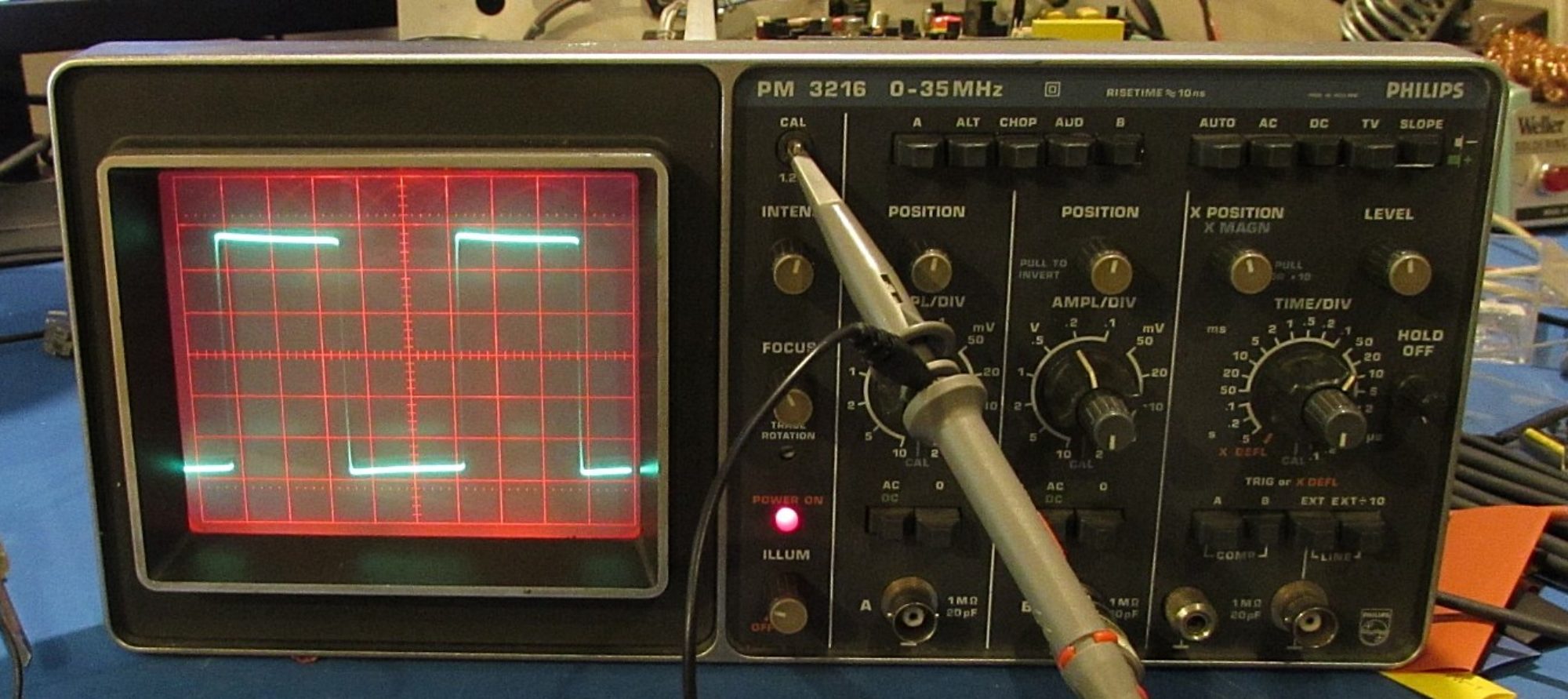
Canadian Vintage Radio Society swap meet. They hold this swap meet every 3 months at a little community hall not too far from home, and I’ve been to this a few times (even with Cranky). Lots of cool old tube radios, and even some transistor ones, along with some interesting (mostly radio) test gear, CB Radios, tube testers etc etc.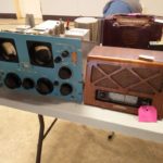
Now back in September I went (dragging along Mrs Boffin as well), and amongst the tables of antiques I managed to score a nice find amongst the radios. Sitting at the side of one of the tables of old radios was an early 1980s era Philips Oscilloscope. Is the scope for sale I asked. Yes, it doesn’t work, but it’s probably just a bad cap the guy responded. It’s yours for ten bucks. INSTA-SALE ! Ten bucks later, and I have a nice project to work on, and perhaps a scope for the bench to add to the (much loved) Analog Discovery.
I get the scope home, and power it up. Seems to kinda/slightly work, I can get a dot in XY mode, but can’t get a timebased trace to appear. So, power supply (at least the HT) seems OK, nothing seems burned inside, this might be repairable.
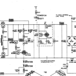 Now time to dry and dig up a manual for this. When I got the chance over the next couple of days to track down a manual for a similar scope at least I had somewhere to start. Thou shall check voltages (according to that Aussie bloke). It didn’t take long to realize that most of the voltage rails were way way off. The 5 volt, was closer to three. It’s an interesting power supply, it takes the mains, recitifies it down to approx 30v then switches that back up to the various voltages required in the scope. Given that what came out of the 1st transformer and bridge (-30V) seemed correct, and that the 2nd transformer had all the voltages on the far side, but only about 60% of them,
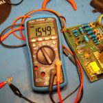 that the problem should lie somewhere in this intermediate supply. First the obvious, from the manual R204 is the output voltage adjust, could it be that easy? No. I could get the voltages to move, but not enough. I pulled a few potentially problem caps to check their ESR, but everything is good. Pulled the switching transitors (V217/218) and they check out OK. At this point I figure it has to be in the what supplies those switching transformers, so I’m checking the voltages around the divider/zeners V211/V212/R204. Voltages around R204 just seems weird, why is there so much voltage across it? Check it with the meter, and sure enough the 220R trimmer is closer to 1k5. At this point I’m dancing around the room, can it be as easy as a bad trimmer. Let’s find out, pull R204, replace it with a 100R/120R pair of resistors and BINGO! The scope SHE’S ALIVE! SHE’S ALIVE!
Of course 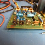 this is in the evening, when nothing is open, so what else to do. One, cleaning, but really it’s not too bad. The outside case is kind of nasty, but a good soapy washing with dish soap and it’s OK. Second, I need to fix the graticule light. One of the two bulbs is burned out, and I did see a youtube video of a guy who replaced it with LEDs. I’ve got lots of LEDs, what colour works best? Green? Blue? White? I settled on red as it’s very high-tech looking. So I carefully removed the old lighting assembly and replaced it with 5 red LEDs and a couple of k of dropping resistor and it works even better than the original. Without fiddling the voltage adjust it goes from 0-100% in the 1st 1/3 of the dial, but who really cares, good enough for the job.
The next day I make the run across town to get a 220R trimmer and replace the old one. Perfect, a fully functional scope for $10 + $2 in trimmers. The auto trigger isn’t great (doesn’t matter, I use manual), and the channel A range switch is really noisy, but a shot of Deoxit solved that (wow, that stuff is good).
Now 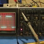 I have a real nice analog scope of my own, my very own. I admit I’ll probably still use the Digilent Analog Discovery more, but there are somethings that a real CRO is very good for.
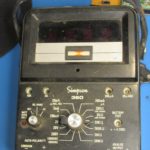
Now, in my most recent visit Mrs Boffin even shot a youtube video of the CVRS swapmeet, and I picked up this Simpson 360 meter, maybe that’s my next project…
