Serial Component Tester

So many things going on, and I’ve been very bad not writing anything in the blog; so here’s a little update on something I’ve started. I picked up one of those inexpensive ATMega-based component testers off AliExpress. It’s a really really neat idea, and works remarkably well for something that’s only $12. Drop in a component and out pops value(s), pinouts etc.

Cheap AliExpress Component Tester

There’s a huge thread on eevblog about them, and Dave even did a video of a another variant, so it was time to play around. This version I picked up has a a bunch of other options such as a basic frequency generator, but I was really just interested in the basic component identification, and a simple LCR meter.

Of course the first thing I wanted to do was fiddle with the software, and actually getting a toolchain that will compile it is a bit of a pain. The code in the git repository that I found wanted a copy of make, but I do my day to day fiddling on a Windows box, so the first problem was trying to find a copy of make for Windows. Turns out that a company called Equation have a compiled version of GNU Make that seems to work better than the one from GNU itself, so I downloaded that as a starting point. Then you need to get the avr compiler for Windows; but isn’t that already present with the Arduino toolchain? The answer is yes, turns out all you really need to do is add:

C:\Program Files (x86)\Arduino\hardware\tools\avr\bin

to your path. Picking all of the various options for my specific version (type of display, encoder etc) was a some reverse engineering, and trial and error, but I’ve succeeded in being able to reprogram an ATMEGA328 (and not the P version, because I was stupid on my last Digikey order) to burn the firmware. At least I have a starting point.

My serial component tester

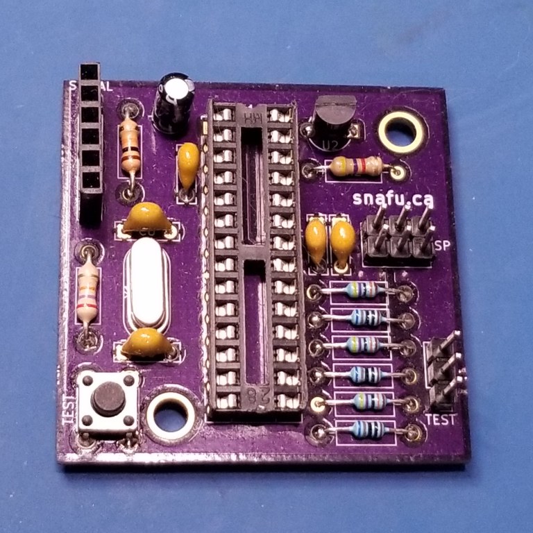
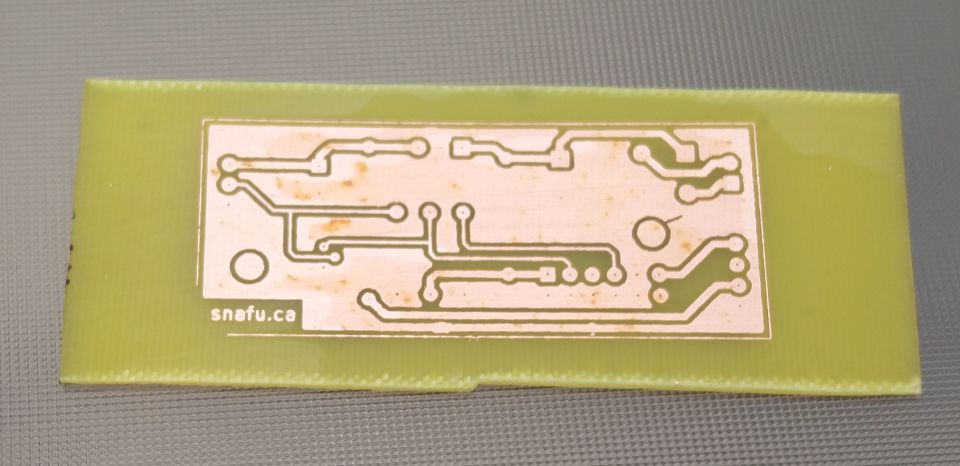
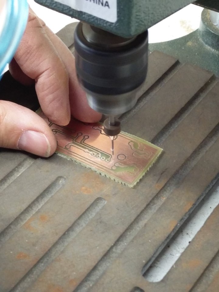
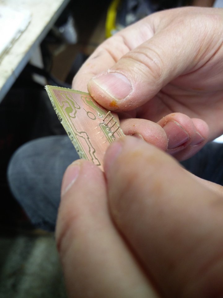
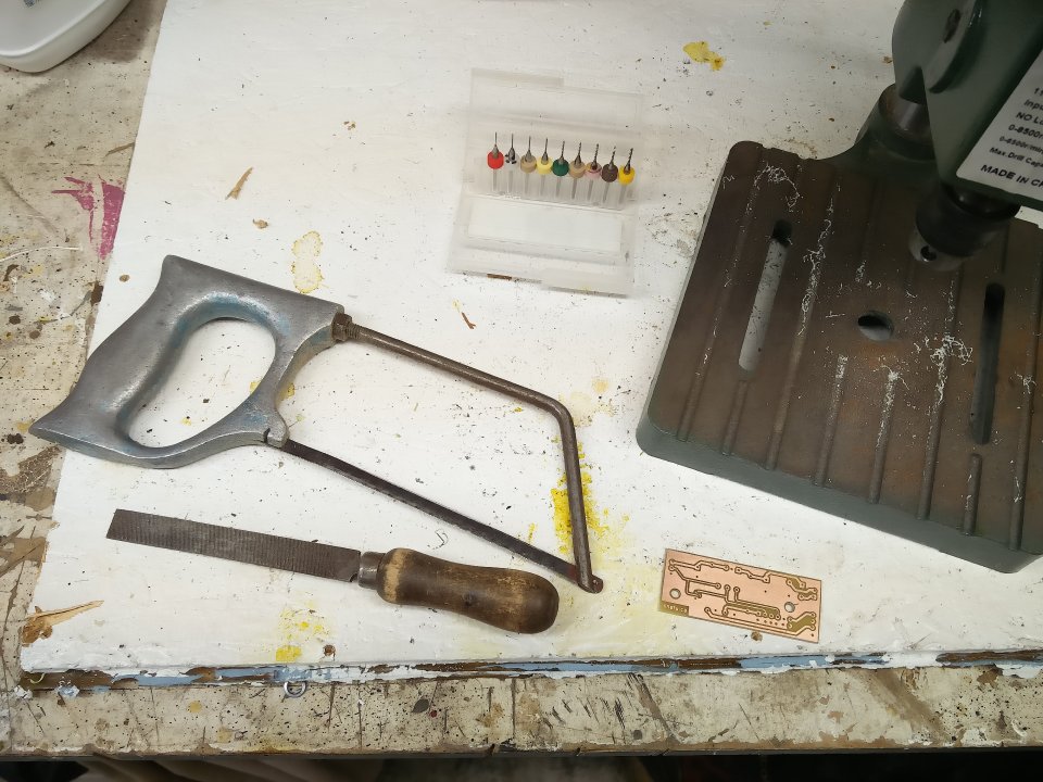
But what I really thought might be fun would be to make a standalone one that could spit data back to my PC, so I hunted online for one of the many circuit diagrams for these testers, and then composed my own version, that speaks serial (I know, how old fashioned). A little work in KiCAD and then fire off the result to OSHPark for some boards (I do love OSHPark). The result is this. I still have a long way to go, because a busy Christmas period has really put this on hold, but I hope to get back to this project really soon.

Over the next month or two (or likely 4) I’m going to try and hack the hardware into having a ‘serial’ display. From my gaze at the one major variant of the code, different displays are handled as separate modules, so I’ll probably have it just output keyvalue pairs, or something like that.

Nixie PSU

I’ve been meaning to make a more permanent power supply board for the nixie project, so over the last couple of weeks I decided on what I wanted. Transformer input, which meant a bridge rectifier, couple of caps, the mount for the DC-DC power supply from tayloredge, a regulator to drive a 5v ATtiny later on, along with a FET to turn on and off the high-voltage output. So I plunked it all into KiCAD (I’m getting better at it), and this is what I came up with. I also decided, I’d try my hand at etching it myself, and take advantage that Misses Boffin had recently purchased a heat press. Maybe I’d be able to do better heat transfers from my Brother laser printer — which are notoriously bad for toner transfer due to a higher temperature toner and fuser than most others (like HP). Well, I played with all sorts of backing, all sorts of temps and time, and came up with pretty much what I had done in the past; old glossy magazine paper. The glossy magazine paper, along with about a minute at 375°F in the heat press gave a pretty good results. After a 10 minute soak in water to pull the paper off, it turned out pretty well. In fact very well, I’ll probably do a lot more this way now that I have a reliable transfer method. Also, I made sure to ground fill the board, so I’ll use less ferric chloride in the future (not that it’s that expensive).


On to etching; I use two pyrix dishes, a larger and a smaller one. Put some hot water (just off the boil in the outer), and then ferric chloride in my inner pyrex dish, (silly me didn’t take a photo), and it took about 6-7 minutes to etch. The moment of truth, rub off the toner (I use a stainless steel dish scrubber to pre-clean and post-clean the board) and what does it look like; it looks great! Drilling is a breeze, I bought this tiny drill press from Rio Grande a few years back,  and it does a great job on PCBs. It has pathetic torque, but when you’re drilling a 0.9mm hole, you don’t need it. With my aging eyesight, I tried using the optivisor to get a better look while drilling, but in this case it doesn’t work that well, as you have to get insanely close to get anything in focus, so I ended up just doing most of it using the bad eyeball method. A few test fits along the way, and it was definitely in the realm of ‘close enough’. Finishing the board I realized I was using the same saw and the same file that I would use to finish veroboard projects from nearly 40 years ago. The saw is an engineering metalwork project from my O-level days (Tin-Man will likely recognize it), and the file was inherited from my grandfather’s stash of tools in the mid-70s.


The final result turned out really well. I managed to not get any pin-outs wrong, the regulator is perfectly at the edge of the board to allow it to mount to the back panel for heatsinking, and most importantly it worked first time. Just need to get a 12V transformer from Lee’s at some point, and fit all of it (transformer, PSU board) along with a switch and fuse and I’ve got the supply all done for my mystery nixie project.

I also spent some time over the weekend playing on another project, but that will be another post, when the last of the parts for that arrives.


PCBs have arrived, and I’m away

Well, the first of two orders of PCBs came back just before I went away on vacation. The first lot I had discussed in my previous blog entry, and was a remake of my stepper gauge project that I sell on Tindie. As my previous experience with OSHPARK, the service is superb. About a 18 day turnaround including crossing the border, free shipping to Canada (not many include that), plus a nice “PERFECT PURPLE PCBS” sticker, which I’ve adorned to my electronics toolbox. If you need a quick(ish) PCB service for a prototype, OSHPARK is pretty close to perfect.

Apparently I did my homework well, because the X27.168 stepper package outline (I found one on the net, but tweaked it further) fits like a glove, unlike my previous revision where I had relied on someone else’s package file and every board required some drilling to fix layout holes. It all looks very nice, and I love the purple, but sadly I didn’t get a chance to assemble one before I left on 3 weeks holiday, all I managed to do is file off the mouse-bites that they used to panelize it.

Once I had become familiar with KiCad, there was no stopping me, so I had also slapped together a little hybrid surface-mount/through-hole project that I’ll use for an electronics class I’ll be teaching in the near future, and ordered them from a company I had read about on EEVBLOG called DIRTYPCBS. When I return, I’m hoping my other PCBs will be sitting waiting for me. I read about this service on EEVBLOG, and it has a few advantages over OSHPARK. Firstly the price; as they’re in Asia (Hong Kong), the price is amazing (US$24 incl shipping for 10 boards 10cm x 5cm). Secondly you have a lot more options such as PCB thickness, soldermask colour, etc etc. I’m quite excited that DIRTYPCBs might become my go-to circuit board provider for anything more than a couple of small samples. Also this board will be my first real foray into SMD (just some 0805s, SOT23 and small LEDs). I’ve avoided SMD as I lack the tools (and eyesight), but wow are the parts ever cheap, one dollar will buy you 300 resistors, or 100 capacitors, or 100 FETs; just incredible. I’ll still try assembling with the old weller iron, but I’m curious to try paste and and a hot air gun.

Also, I did some reading (and viewing on YouTube) of people doing hybrid hot/cold transfer for laser printer transfers. I have made single sided PCBs using the laser printer transfer method and an iron, but it took a fair bit of experimenting to discover that with my brother laser printer that only glossy magazine paper really worked for laser printer transfers. Two things have changed; one I discovered people are using a mixture of acetone/isopropyl alcohol on the PCB surface prior to transfer to slightly disolve the toner, and secondly Misses Boffin has purchased a heat press (for doing vinyl transfer), so I have a better heat press with likely more even heating/pressure.

Hmm, I wonder if I can just cut a PCB mask using a silhouette vinyl cutter. Must look into that, that might work too.