Nixie PSU

I’ve been meaning to make a more permanent power supply board for the nixie project, so over the last couple of weeks I decided on what I wanted. Transformer input, which meant a bridge 
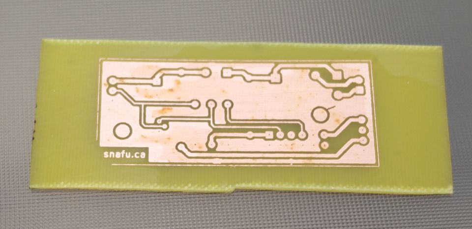
rectifier, couple of caps, the mount for the DC-DC power supply from tayloredge, a regulator to drive a 5v ATtiny later on, along with a FET to turn on and off the high-voltage output. So I plunked it all into KiCAD (I’m getting better at it), and this is what I came up with. I also decided, I’d try my hand at etching it myself, and take advantage that Misses Boffin had recently purchased a heat press. Maybe I’d be able to do better heat transfers from my Brother laser printer — which are notoriously bad for toner transfer due to a higher temperature toner and fuser than most others (like HP). Well, I played with all sorts of backing, all sorts of temps and time, and came up with pretty much what I had done in the past; old glossy magazine paper. The glossy magazine paper, along with about a minute at 375°F in the heat press gave a pretty good results. After a 10 minute soak in water to pull the paper off, it turned out pretty well. In fact very well, I’ll probably do a lot more this way now that I have a reliable transfer method. Also, I made sure to ground fill the board, so I’ll use less ferric chloride in the future (not that it’s that expensive).


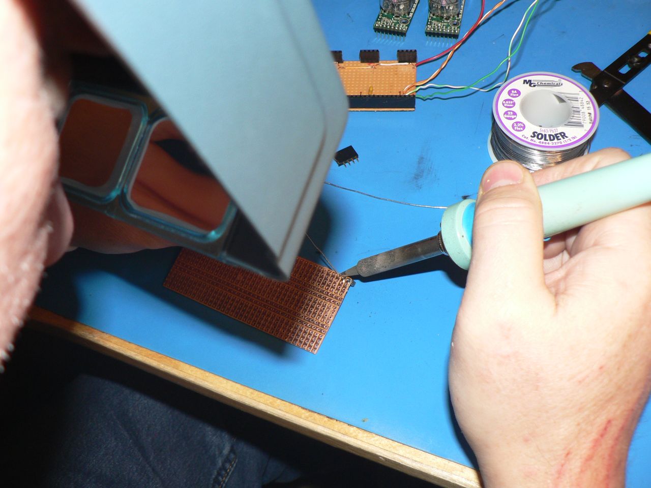
On to etching; I use two pyrix dishes, a larger and a smaller one. Put some hot water (just off the boil in the outer), and then ferric chloride in my inner pyrex dish, (silly me didn’t 
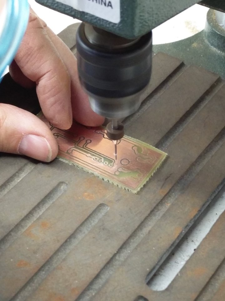
take a photo), and it took about 6-7 minutes to etch. The moment of truth, rub off the toner (I use a stainless steel dish scrubber to pre-clean and post-clean the board) and what 
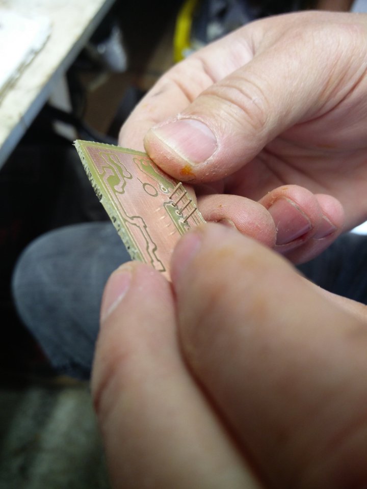
does it look like; it looks great! Drilling is a breeze, I bought this tiny drill press from Rio Grande a few years back,  and it does a great job on PCBs. It has pathetic torque, but when you’re drilling a 0.9mm hole, you don’t need it. With my aging eyesight, I tried using the optivisor to get a better look while drilling, but in this case it doesn’t work that well, as you have to get insanely close to get anything in focus, so I ended up just doing most of it using the bad 
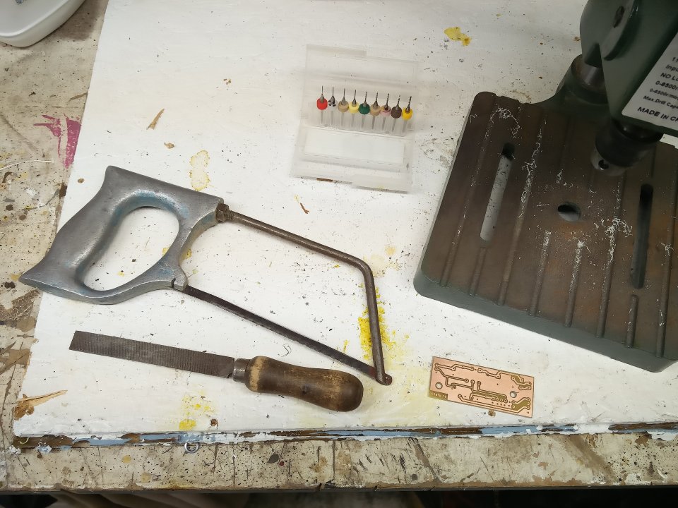
eyeball method. A few test fits along the way, and it was definitely in the realm of ‘close enough’. Finishing the board I realized I was using the same saw and the same file that I would use to finish veroboard projects from nearly 40 years ago. The saw is an engineering metalwork project from my O-level days (Tin-Man will likely recognize it), and the file was inherited from my grandfather’s stash of tools in the mid-70s.


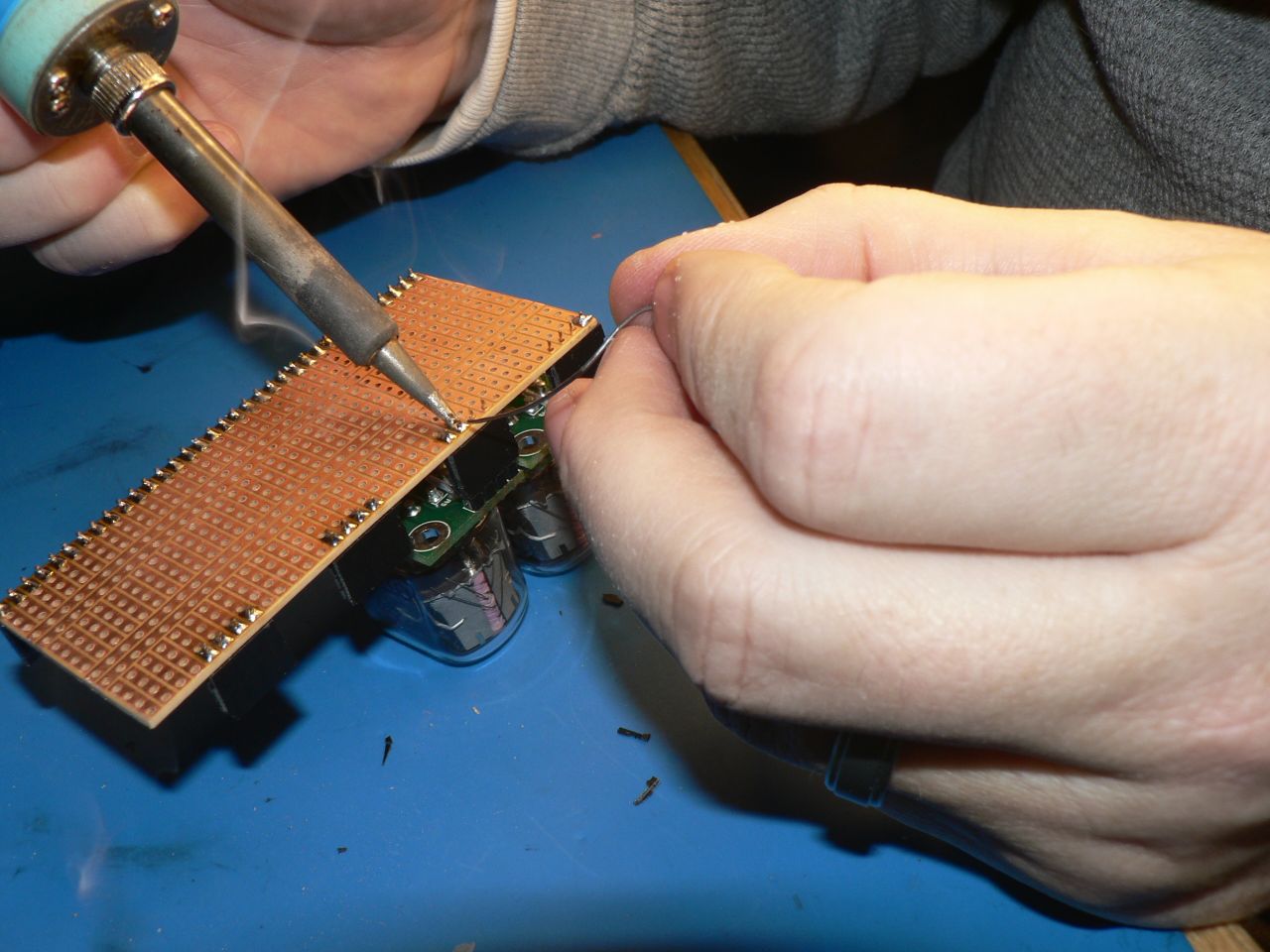
The final result turned out really well. I managed to not get any pin-outs wrong, the regulator is perfectly at the edge of the board to allow it to 
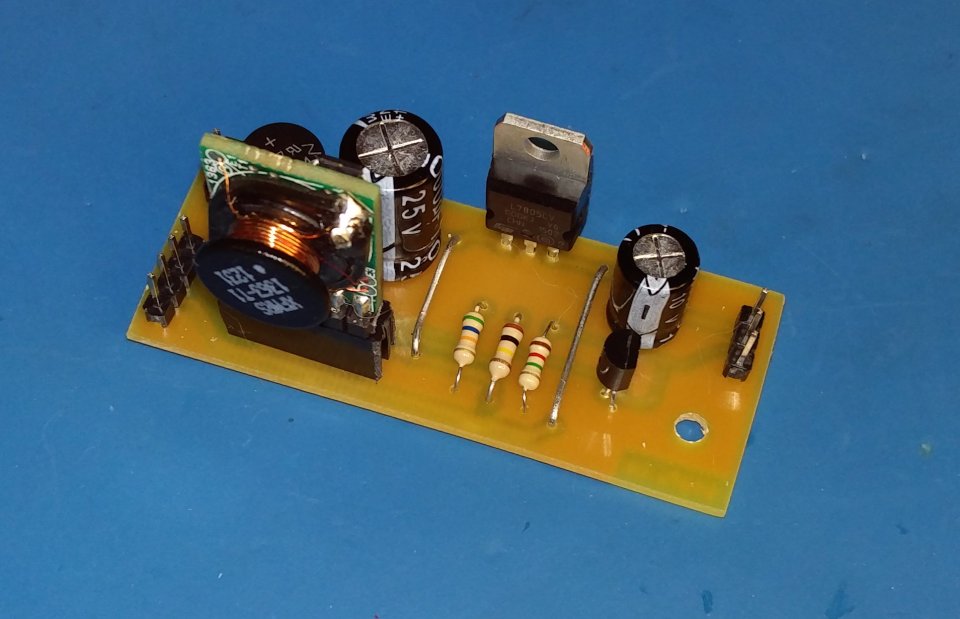
mount to the back panel for heatsinking, and most importantly it worked first time. Just need to get a 12V transformer from Lee’s at some point, and fit all of it (transformer, PSU board) along with a switch and fuse and I’ve got the supply all done for my mystery nixie project.

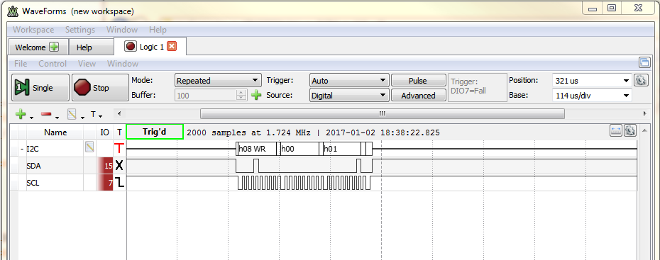
I also spent some time over the weekend playing on another project, but that will be another post, when the last of the parts for that arrives.


Donegan OptiVisor

Donegan OptiVisor DA-5

I’d been ummming and ahhhing about getting something like for years. Would it work? Would it work better than my existing magnifying lamp? I had some credit on Amazon.ca, so I finally bit the bullet and purchased it. I also had Prime one-day shipping (purchased to watch the the Grand Tour), so it came the next day without any additional shipping charges. In fact they originally offered to ship it same day when I looking online mid-day, but I waited until the evening to order as I knew that Mrs Boffin would be home the next day when it arrived. So after settling in to watch the latest “The Reassembler“, what should appear on the screen, but James May sporting pretty much the same thing. Perhaps I was James May in a previous life, I’d like to think so (or maybe it’s my future life?).

How does it work? It’s superb for close-up work. Amusingly, the first task I put it to use with was putting a new screw back in my distance glasses, after it fell out yesterday. Tweezers, small screw, small screwdriver. Success, first time. Run, don’t walk and buy one of these, you wont regret it.

Focal distance is about 20cm which is close, but not so close that it gets in the way of the soldering iron, which means I did well when I chose the 2.5x version; the higher magnification ones having a lower working distance. The stereo eyepieces (glass on the DA version) seem nice and sturdy, and I splurged the extra $13 for additional “OptiLoupe” flip down magnifier which gives another 2.5x for a total of 6.25x for very close up work. With the extra magnifier flipped down, I can easily read part numbers off SMD parts; worth the extra dollars.

Wow, the flash really makes my short haircut look like I'm bald.

Back to work on the nixie project I thought I’d try it out this evening making a second nixie back-plane like last weekend’s, mostly just to see what it’s like to solder with it on. I really like it. There’s only one small complaint and that is the bottom edge of the headband is sharpish plastic and is a little uncomfortable on my ears, but other than that the headband works well, it’s not heavy at all, and doesn’t feel unstable or awkward in any way. I’ll probably just put a little piece of fabric on the headband, and that will completely solve any annoyance.

Lastly, and completely unrelated, I of course mucked up somewhat and made a mistake soldering, so dug out some solder-wick to fix it. I had this cheapo roll of Chinese wick from Ali Express and I thought I’d give it a try (normally I use the 25 yr old roll of MG). Anyway, the Chinese stuff was useless, and would pick up nothing. Until, that is, I wetted the wick with an MG Flux pen. If you’re not using wick without a flux pen first, you need to run, not walk, and go buy a good flux pen (keep it in a zip-lock when you’re not using it).


Nixies

Bare Nixie Board

I had been thinking about doing a little project with nixies for a long time, but hadn’t really gotten around to it. They have a great old-school (old-fart?) vibe, and I found an old board on eBay with 7 nixies on it for cheap and decided that was a good place to start. It arrived (from Belarus), and I quickly realized how much faster this would go with a proper vacuum desolder tool, rather than just a sucker and some wick. Anyway, after much futzing around, I managed to get the little tubes off the board in prep for the next step. There are still some high voltage drivers left on that board I wouldn’t mind scavenging, but the board has a coating, and those intial 7 tubes just about killed me.

Nixies need 170V or so, and I didn’t much fancy the idea of rolling my own high-voltage power supply, so a quick check of the interwebs and sure enough there are a ton of them on places like eBay and Tindie. However, one that caught my attention as a better solution was a guy down in the states with a website tayloredge.com. Not only did he have some nice inexpensive (and tiny) power supplies, they also sell a very very nifty I2C nixie driver board. I had originally thought I might build a two digit module with the shift registers and drivers and sell it on Tindie myself, but wow, this is much better supporting direct addressing, shift modes, clock modes and even dimming. The density is crazy, with tiny SMD high voltage drivers, and a PIC controlling it all.

Like all good projects, all this stuff arrived months ago, and sat on my desk while I goofed off and did other things (Oscilloscope episode, coming soon !), and finally this weekend I decided to hook some of it up. First task was to make a mounting board that held four nixie modules (I only have two right now – I need to order more), so I cut up some advanced-vero-substitute (which really brings back old memories of Vero offcuts @ Greenweld), and build that into a mount that holds four digits, and strings together the necessary power (170, 5, GND) and I2C (SDA, SCL) lines.

A little cutting, filing, and some 0.1″ headers soldered to the board and it works out pretty well. Eventually I want two boards of four, but for now I’ll get the first one hooked up, and then spend some time playing with the I2C interface. I tried really hard to get some action shots of the soldering but that’s pretty hard without an assistant, luckily Mrs Boffin was close at hand, so I did manage to capture at least one action shot.

In the end I decided to also add a couple of 0.1μF capacitors as well on the 5 volt rail, but it all went together fairly well, all I need to do now is repeat it on the second board. It really is nice to have a stock of things like the 0.1″ headers and caps, which I buy cheap in bulk from China/AliExpress.

I had already tested out the power supply just on a bare nixie tube, and had learned that you needed a 47k voltage setting resistor as well as an enable jumper, so it was simple to put the power supply module on a little Arduino shield, along with the I2C pullups, and then I can just use that as a test jig. Amazingly the PSU works great from 5 volts with enough oomph to drive a couple of tubes, although I suspect in the final circuit with eight nixies, I’ll probably need to run the PSU from 9-12V.

Now the simple part, right? A little Arduino sketch that outputs the data to the tubes. Of course by this time it’s 11pm, and while it seemed straight forward from the Wire library in Arduino-land that this should be simple, things rarely are.

After everything was hooked up and on the board I was having all sorts of problems. Hey! This should be easy, set the address, send a register value, send a digit value. Not so fast bucko. First I managed to bend a pin on the bottom of the shield that connects it to the Arduino. Did I bend just any pin? No… I bent the ground pin, on the far side, bent into the middle, so it was impossible to see until I finally flipped the shield upside down, followed by a facepalm moment. Still with all of that working again, I could see that there was I2C data being sent, but nothing was showing up on the digits.

This should send a 5 to the first module:

Wire.beginTransmission(0x10);
Wire.write(0); // register
Wire.write(5); // value
Wire.endTransmission();

Nope, still no output on the tubes. After much head scratching, (and a 2nd glass of ginger beer), I decided it was time to dig out something that could actually decode what was going on on the I2C bus. So into the tool chest and out with the Analog Discovery USB oscilloscope I bought a couple of years back. I had picked this up off Kijiji from a student at USask that didn’t grasp the concept that the $100 student price he paid for it was WAAAY less than the $275 street price for us normal people. I see two or three every year going cheap this way. Anyway, it’s a fine tool, and while the bandwidth isn’t going to win any awards, it has built-in I2C  decoding on the 16 channel logic analyzer. Hey, what’s all that extra traffic happening? I didn’t put that there. Turns out it the module was set in clock mode (as opposed to address mode). WTF ?  The answer is that when they say “0 0 0 0” for the DIP switches, they really mean “ON ON ON ON” because they’re shorting to ground on pulled high inputs. OK, now we’re cookin’ with gas. Set it up to the self test setting, voila! It’s counting from 0-9. Set it back to the 1st address (0x10), but still my simple sketch isn’t doing the business, why not ?  I’ve set it to the correct address, I now understand the switch settings, why? why?  Well after playing with the sketch for different addresses, I discovered that when they say address 0x10 in the docs, they really mean half of that (I2C addresses are 7 bits and they were counting from the MSB apparently), Changing the address from 0x10 to 0x08 and it’s working YAY!

Once I got everything working, you can see clearly that the I2C address (at least from the Analog Discovery/Waveforms software) the address is and should be 0x08, not 0x10 for the 1st address. Easy fix in the code, and now I’ve got this sucker counting from 00-99 under my control.

Well, that was a weekend of 60 second fixes taking hours to find. Anyway, the first couple of digits are working, now to get 6 more modules (I’ve already got the nixies), and the 2nd carrier board built and we can move onto the next stage of the project.