There are a lot of tutorials on the net on how to do this, but nowhere is there a single, simple concise list of how to hook it up, and how to actually program a raw chip using the Arduino eco-system; so here we go.
- Program your UNO (or other Arduino) to be an In System Programmer (ISP) to program bare chips. This is just like programming any other Arduino sketch.
- File; Examples; 11 Arduino ISP; Arduino ISP
- Sketch; Upload
- Now you need to add the definitions for the ATTiny/ATMega chips. The development environment doesn’t come with them, so you have to add them manually.
- File; Preferences; Additional Boards Manager URLs:
http://drazzy.com/package_drazzy.com_index.json (ATTiny)
https://mcudude.github.io/MiniCore/package_MCUdude_MiniCore_index.json (ATMega) - Tools; Board; Boards Manager; enable “ATTiny Core” or “Mini Core” as appropriate
- File; Preferences; Additional Boards Manager URLs:
- When you’re programming the CPUs directly, there are more settings than just for an Arduino. Things like clock, clock internal/external etc. These settings are stored on an AT processor in what is referred to as “the fuses”.
- Tools; Board; ATTiny 25/45/85 (or ATMega 328)
- Tools; Chip/Variant; ATTiny 85 (or ATMega 328)
- Tools; Clock; 8MHz (internal)
- Tools; Programmer; Arduino as ISP
- Tools; Burn Bootloader (this really configures the chip’s fuses)
- Write Code, just like you would before.
- Sketch; Upload Using Programmer (Shift-Ctrl-U)
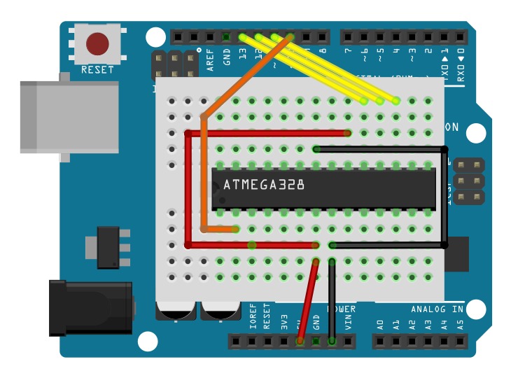
That last step is the one that’s easy to get stuck on, and just hitting upload doesn’t work (on the ATMega), because it assumes it’s an Arduino, you have to say “Upload Using Programmer”.
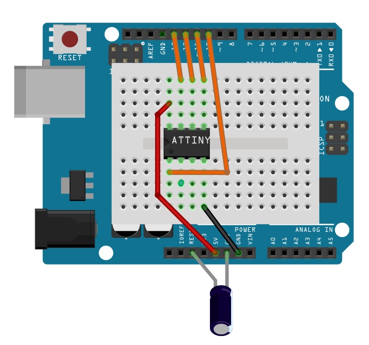
Lastly, you’ll need some diagrams of how exactly you hook it all up, so here it is. That capacitor on the ATTiny layout is 10uF between Reset and Ground.