Wow, three years a long time between blog posts. It’s not that I haven’t been busy, I have. In fact so busy, that I haven’t had a chance to really do anything blog-worthy for a long time.
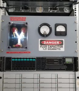
So here it is, a new project; the Flux Capacitor. Someone gave me the idea for this many many years ago, and it’s only now that I’ve finally got around to building it, and making a video about the build.
https://www.youtube.com/watch?v=2kqEiJ2V138
The server rack at work was really looking kind of bare, and in reality we also had some temporal displacement issues to stabilize, so what all server rooms really need is a Flux Capacitor. The video has the full build details, but I’ll add the parts list here, along with a few photos of the build that didn’t make it into the video.
It started off as a plastic box with a clear lid, and other than that, pretty much everything else in the build is readily available hobby or computer parts from your favourite online retailer in China, or your local hardware store. Add to that, supplies you had around the garage; old bits of wire, paint, glue.

The secret to all of this is what Adafruit call “NeoPixels”, and what the rest of the world call WS2812 LED tape. This stuff is inexpensive ($10/m). For this project you do want to ensure you have the 144 LEDs/metre version of it to get the best effect. I originally bought some that was only 60 LEDs/m and it just wasn’t up to the task

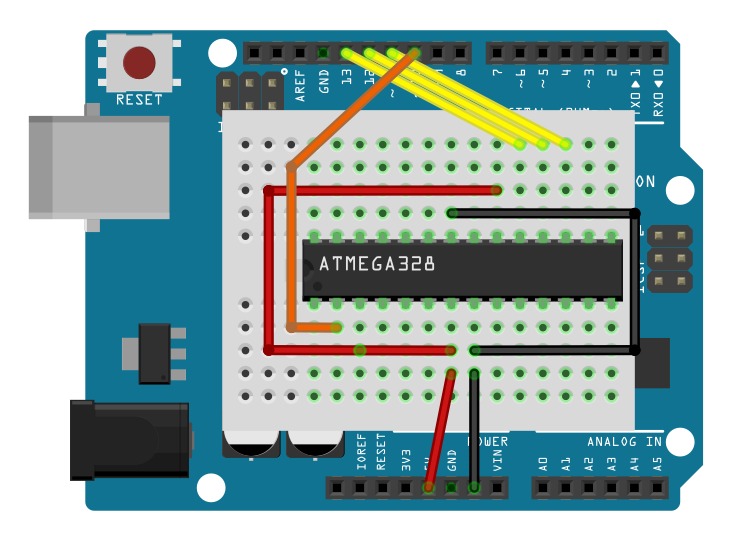
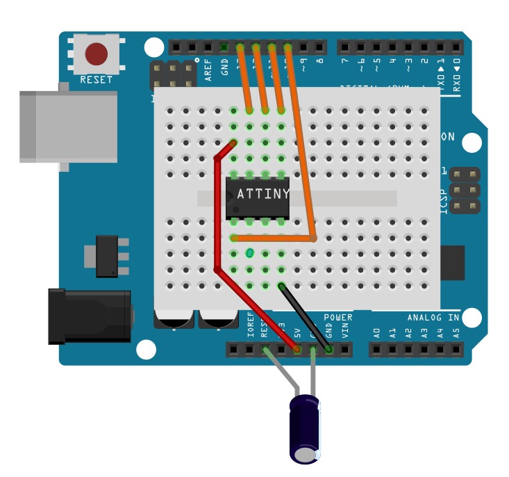
The LEDs and the meters are controlled using an Arduino Pro Mini (although I’d recommend the nano with the built-in USB). This diagram here shows how the pro-mini is wired to the other couple of components on the protoboard. Resistors to drive the meters (on the left) and a 100μF capacitor (power supply smoothing), and a 220R resistor to drive the LED tape.
The source code is just over 100 lines in the Arduino IDE, and you can download it from GitHub at https://github.com/snafu-ca/fluxcondenser

Parts List
6U Blank Panel (Hammond PBFS19010BK2)
Arduino Pro Mini or Pro Nano (latter recommended)
Plastic Enclosure Box, Clear Cover – AliExpress
Spark Plug Caps – AliExpress
LED Tape 1m of 144 LED/m – AliExpress
10mm Acrylic sheet – AliExpress
10mm Acrylic rod – AliExpress
Warning Sticker – AliExpress
1″ PVC End Cap – Local Hardware Store
RG59 cable TV Wire
Paint, Primer, Sandpaper
Various Nuts/bolts/screws