Furnace Woes

Woke up yesterday morning to a gas furnace that wouldn’t light. It’s an older Bryant (Carrier), but it has been working well, and we don’t burn enough gas over the year that the $5,000 investment in a new one would be worth it.

Step 1, let’s see what is and isn’t working.

  • Main fan seems to be working on power up – CHECK
  • Inducer fan is running prior to attempting to light – CHECK
  • Ignitor lights (glows) – CHECK
  • Gas valve isn’t opening – THERE’S YOUR PROBLEM MURIEL

It doesn’t appear to open the gas valve – Hmmm. Now all of the connections run from the various parts to the control board on an edge connector, it couldn’t be that easy could it? Out with the Deoxit, quick spray, no difference.

Next, let’s buzz out the gas valve. Is there resistance? Yep, should be good. Disconnect the gas valve from the board and try it straight across the 24V from the transformer that powers the circuit board, and the gas valve opens.

That means something is up on the main board. Seems to be a pretty popular board (Carrier CES0110057-01). to the point where there’s a company (ICM Controls) making a compatible board ICM281, for a pretty decent price — if you happen to live in the USA — sadly it’s nearly double here in Canada; over $400, but still better than the $700 the furnace guys all quoted.

Carrier CES0110057

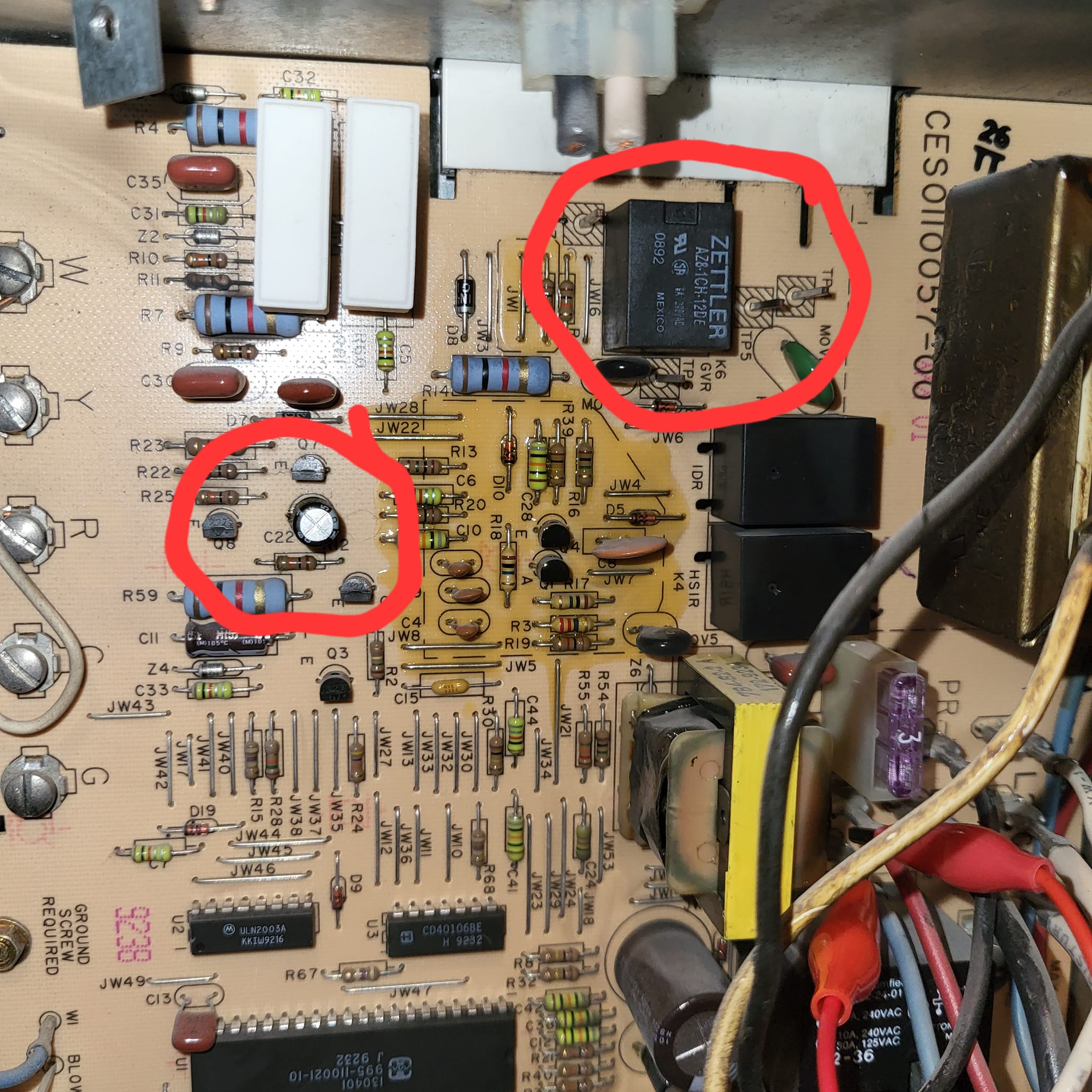
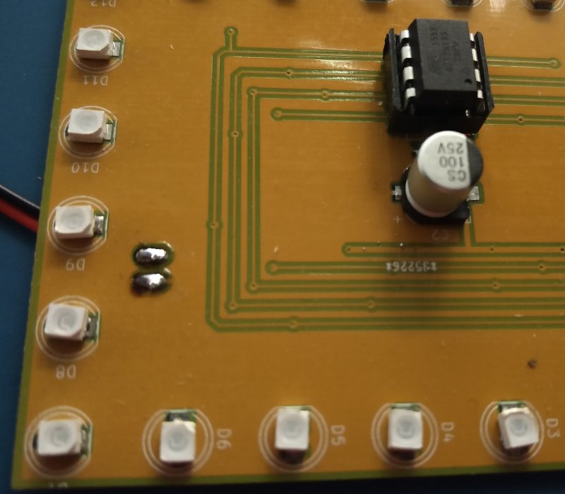
My initial guess is that it’s the relay, well relays are cheap, I even have one in the parts bins I could use, so let’s give that a whirl before we drop $400 on a new board. Pulled the board out, desoldered the relay (Zettler, a brand I’d never heard of before), and tried it on the bench. click click click, the relay is just fine. Damn.

leaky leaky

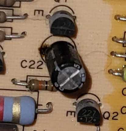
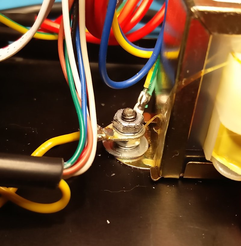
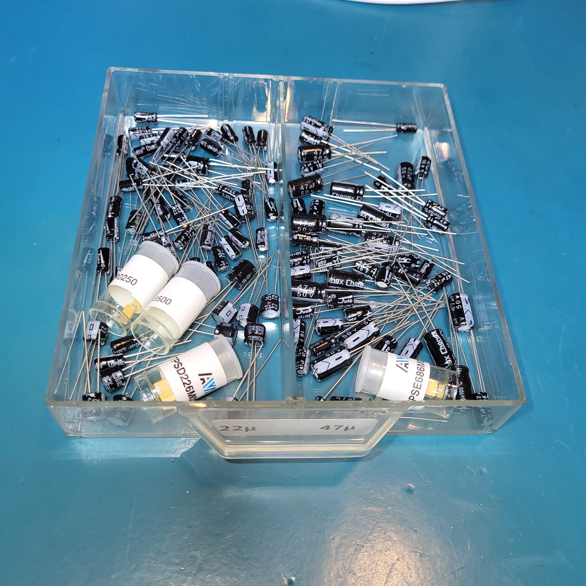
Let’s make sure everything driving it is OK. Traced the connections back to a capacitor, and hey, what’s this, looks like maybe this capacitor has let go after 25yrs. Desolder the cap, and sure enough there’s electrolyte leaking out the bottom. Clean off the board with some isopropyl, and drop in a new cap from the parts cabinets (47μF/50V). A new 5¢ capacitor certainly isn’t going to do any harm.

spare 47u capacitors

Re-installed the control board, and what do you know, it fires right up first time. YAY !

Now off to put on a nice cup of tea and write a blog post about this….

Flux Capacitor

Wow, three years a long time between blog posts. It’s not that I haven’t been busy, I have. In fact so busy, that I haven’t had a chance to really do anything blog-worthy for a long time.

So here it is, a new project; the Flux Capacitor. Someone gave me the idea for this many many years ago, and it’s only now that I’ve finally got around to building it, and making a video about the build.

https://www.youtube.com/watch?v=2kqEiJ2V138

The server rack at work was really looking kind of bare, and in reality we also had some temporal displacement issues to stabilize, so what all server rooms really need is a Flux Capacitor. The video has the full build details, but I’ll add the parts list here, along with a few photos of the build that didn’t make it into the video.

It started off as a plastic box with a clear lid, and other than that, pretty much everything else in the build is readily available hobby or computer parts from your favourite online retailer in China, or your local hardware store. Add to that, supplies you had around the garage; old bits of wire, paint, glue.

The secret to all of this is what Adafruit call “NeoPixels”, and what the rest of the world call WS2812 LED tape. This stuff is inexpensive ($10/m). For this project you do want to ensure you have the 144 LEDs/metre version of it to get the best effect. I originally bought some that was only 60 LEDs/m and it just wasn’t up to the task

The LEDs and the meters are controlled using an Arduino Pro Mini (although I’d recommend the nano with the built-in USB). This diagram here shows how the pro-mini is wired to the other couple of components on the protoboard. Resistors to drive the meters (on the left) and a 100μF capacitor (power supply smoothing), and a 220R resistor to drive the LED tape.

The source code is just over 100 lines in the Arduino IDE, and you can download it from GitHub at https://github.com/snafu-ca/fluxcondenser

Parts List

6U Blank Panel (Hammond PBFS19010BK2)
Arduino Pro Mini or Pro Nano (latter recommended)
Plastic Enclosure Box, Clear Cover – AliExpress
Spark Plug Caps – AliExpress
LED Tape 1m of 144 LED/m – AliExpress
10mm Acrylic sheet – AliExpress
10mm Acrylic rod – AliExpress
Warning Sticker – AliExpress
1″ PVC End Cap – Local Hardware Store
RG59 cable TV Wire
Paint, Primer, Sandpaper
Various Nuts/bolts/screws

Soldering Iron Shootout

About a year ago I was teaching an after-work intro electronics class, and I picked up a couple of cheap Yihua 947-II soldering irons for giveaways.

There was some discussion about other lower cost alternatives, so I decided to get in a few low-cost options, to compare, including a Quicko 951-T12 (Hakko clone) and the very popular TS100 battery powered iron.

Here’s my results of the comparison.

OPUS BT-C3100

Another couple of weeks, and time for another video. This time I’m talking about my new OPUS BT-C3100 battery charger from AliExpress.

I had wanted to experiment with some LiOn batteries, and after building a very crude discharge tester for the shaver repair, I decided I needed something a littl more substantial. People seem to like this charger, so $30 and 3 weeks later, here it is.

You can watch the unboxing video here.

Battery replacement

I’m transitioning to putting a lot of my content on YouTube, so this wont be a long blog post, just a reference to the video.

The battery in my Braun shaver had slowly been getting worse and worse, and it was succumbing to higher and higher internal resistance. Luckily the Braun takes a completely normal AA NiMH battery, and the shavers are built to be fixed, so it’s a relatively easy task to take it apart and replace the batteries.

And just to show that we can’t all be perfect, watch the video and see what I did wrong !

OpenEVSE

A few months ago we purchased a new electric car. It’s a Volkswagen eGolf, and it’s amazing. Here are the specs:

BOFFIN
Boffin
  • 35kWh battery, approx 225km range
  • 100kW (134hp) electric motor and 214 ft-lbs of torque
  • 15.5kWh / 100km power consumption. That’s at C$0.08085/kWh or $1.32 for 100km; or about 0.9 litre / 100km with local gas prices
  • It looks normal – the stealth electric car, people don’t even realize VW make one

However, it also meant that I had to do something about charging it at home. Locally there are quite a few public chargers and they’re easy to find with PlugShare, but ideally it would be better to charge at home. I could use the supplied 120V / 10A charger, but that would mean a full charge from empty would take a day and a half, and that probably wouldn’t be the most convenient (although my friend Burt does do that with his Leaf).

I should clarify things a bit here, it’s not really a charger, the charger itself is built into the car, an EVSE (electric vehicle supply equipment) just tells the car how much electricity it can pull, and has a couple of safety checks to cut power unless it’s plugged in, this means than an EVSE isn’t really that complicated.

My garage is already wired for 240V and has a nice 30A / 240V outlet (NEMA 14-30R aka a dryer outlet for those that care about part numbers) for a welder so the only real task was to source a 24A (80% continuous load on a circuit) level 2 EVSE. Oddly it’s an unusual value, 16A and 32A (for 20 & 40A circuits) are common, but the in between wasn’t quite so easy. There are a few commercial ones out there, but they’re really quite a lot more money than the 16A ones, and what the heck, building one is more fun.

  • it would work now @ 24A, and could work at higher (or lower) current in the future
  • could make it a plug in version (and hardwired later), this would also allow me to ‘take it on the road’
  • had a smart WiFi interface
  • building things is fun
Building and filming the EVSE build

Another departure about doing this project is that I filmed the whole thing, and placed it on youtube. This was a new endeavour for me, and took a lot of fiddling, camera work, microphones, and video editing that I hadn’t touched before. I think it turned out OK, and I’m eagerly awaiting what people have to say.

The EVSE works well, and the only real issues with the assembly are that the instructions are not super obvious, and that there are two wires that they join in a silly silly way (using a 2 pin header), so you don’t have to solder it. I just soldered it.

Web Interface to OpenEVSE

Programming ATMega and ATTiny chips using the Arduino IDE

There are a lot of tutorials on the net on how to do this, but nowhere is there a single, simple concise list of how to hook it up, and how to actually program a raw chip using the Arduino eco-system; so here we go.

  • Program your UNO (or other Arduino) to be an In System Programmer (ISP) to program bare chips.  This is just like programming any other Arduino sketch. 
    • File; Examples; 11 Arduino ISP; Arduino ISP
    • Sketch; Upload
  • Now you need to add the definitions for the ATTiny/ATMega chips. The development environment doesn’t come with them, so you have to add them manually.
  • When you’re programming the CPUs directly, there are more settings than just for an Arduino. Things like clock, clock internal/external etc. These settings are stored on an AT processor in what is referred to as “the fuses”.
    • Tools; Board; ATTiny 25/45/85 (or ATMega 328)
    • Tools; Chip/Variant; ATTiny 85 (or ATMega 328)
    • Tools; Clock; 8MHz (internal)
    • Tools; Programmer; Arduino as ISP
    • Tools; Burn Bootloader (this really configures the chip’s fuses)
  • Write Code, just like you would before.
    • Sketch; Upload Using Programmer (Shift-Ctrl-U)

That last step is the one that’s easy to get stuck on, and just hitting upload doesn’t work (on the ATMega), because it assumes it’s an Arduino, you have to say “Upload Using Programmer”.

Lastly, you’ll need some diagrams of how exactly you hook it all up, so here it is. That capacitor on the ATTiny layout is 10uF between Reset and Ground.


Serial Component Tester

So many things going on, and I’ve been very bad not writing anything in the blog; so here’s a little update on something I’ve started. I picked up one of those inexpensive ATMega-based component testers off AliExpress. It’s a really really neat idea, and works remarkably well for something that’s only $12. Drop in a component and out pops value(s), pinouts etc.

Cheap AliExpress Component Tester

There’s a huge thread on eevblog about them, and Dave even did a video of a another variant, so it was time to play around. This version I picked up has a a bunch of other options such as a basic frequency generator, but I was really just interested in the basic component identification, and a simple LCR meter.

Of course the first thing I wanted to do was fiddle with the software, and actually getting a toolchain that will compile it is a bit of a pain. The code in the git repository that I found wanted a copy of make, but I do my day to day fiddling on a Windows box, so the first problem was trying to find a copy of make for Windows. Turns out that a company called Equation have a compiled version of GNU Make that seems to work better than the one from GNU itself, so I downloaded that as a starting point. Then you need to get the avr compiler for Windows; but isn’t that already present with the Arduino toolchain? The answer is yes, turns out all you really need to do is add:

C:\Program Files (x86)\Arduino\hardware\tools\avr\bin

to your path. Picking all of the various options for my specific version (type of display, encoder etc) was a some reverse engineering, and trial and error, but I’ve succeeded in being able to reprogram an ATMEGA328 (and not the P version, because I was stupid on my last Digikey order) to burn the firmware. At least I have a starting point.

My serial component tester

But what I really thought might be fun would be to make a standalone one that could spit data back to my PC, so I hunted online for one of the many circuit diagrams for these testers, and then composed my own version, that speaks serial (I know, how old fashioned). A little work in KiCAD and then fire off the result to OSHPark for some boards (I do love OSHPark). The result is this. I still have a long way to go, because a busy Christmas period has really put this on hold, but I hope to get back to this project really soon.

Over the next month or two (or likely 4) I’m going to try and hack the hardware into having a ‘serial’ display. From my gaze at the one major variant of the code, different displays are handled as separate modules, so I’ll probably have it just output keyvalue pairs, or something like that.

Surface Mount

Well, I bit the bullet and decided I really needed to learn how to do surface mount, so I went and bought this Sigma R700 Hot Air rework station from Amazon. Looks to be an exact clone/rebrand of the really popular 858D, but for C$75, it seemed like a deal. Now that I’ve got it, it seems to do what it’s supposed to do, and lacking any comparative tools to try it against, I’ll call it great. Weirdly after buying it, a whole bunch of fraud-sellers appeared on amazon.ca selling it for $25, but then they all disappeared, and now all I see is the 858 for similar money.

I have seen a couple of warnings about poor grounding, and I thought while I was writing this I should probably should take it apart to check, so I changed the ground routing for the nozzle straight through to the ground lug on the transformer. Dave did a review of a very similar (but has a different PCB to mine) 858D version, which is worth watching. Anyway, onto actually using it….

Of course this all meant that I started to run out of room on my desk, so I built a little shelf to put my soldering equipment and PSU on, and it leaves more room for the meters and what I’m working on further down. Amazing how one thing always seems to lead to another.


Anyway, onto soldering, but of course I needed some solder paste, so a quick Amazon prime (ordered at 10:30 one night,  delivered the next day) for some MG Chemicals solder paste (really not worth skimping on some off-brand with solder), and I got to work. I had watched a bunch of various videos, but developed my own system of small blobs of solder paste, and then hitting it up with the hot air gun. I keep the solder paste in the fridge (apparently it will last longer), but didn’t really give it enough time to fully warm up, it is a little easier to work with when it’s room temperature.

Below are a couple of photos of my handywork, and it’s actually quite a bit easier than I ever expected. By trial and error I discovered that I need a little less solder paste than expected, and by waving the magic wand (hot air blower) over the board for a few seconds it all nicely melted into place. I was working with 0805 resistors, and sot23 FETs so I suppose things could be more difficult, and I noticed this kit on Tindie for those really inclined to try and punish themselves.
In the end I think it all turned out pretty well.  The components are soldered into place, and it doesn’t look like too much of a botch job. On the top side for fun I decided I’d try puting some SMT LEDs in the place of where the through-holes would have gone. You end up using a little more solder than normal as some goes down into the hole, but it also seemed to work pretty well (although I did get a couple of LEDs in backwards the first time.. That’s pretty easy to mess up).

The observant people out there will also notice I missed two traces on my PCB, I’ll let you try and locate the jumpers.


Nixie PSU

I’ve been meaning to make a more permanent power supply board for the nixie project, so over the last couple of weeks I decided on what I wanted. Transformer input, which meant a bridge rectifier, couple of caps, the mount for the DC-DC power supply from tayloredge, a regulator to drive a 5v ATtiny later on, along with a FET to turn on and off the high-voltage output. So I plunked it all into KiCAD (I’m getting better at it), and this is what I came up with. I also decided, I’d try my hand at etching it myself, and take advantage that Misses Boffin had recently purchased a heat press. Maybe I’d be able to do better heat transfers from my Brother laser printer — which are notoriously bad for toner transfer due to a higher temperature toner and fuser than most others (like HP). Well, I played with all sorts of backing, all sorts of temps and time, and came up with pretty much what I had done in the past; old glossy magazine paper. The glossy magazine paper, along with about a minute at 375°F in the heat press gave a pretty good results. After a 10 minute soak in water to pull the paper off, it turned out pretty well. In fact very well, I’ll probably do a lot more this way now that I have a reliable transfer method. Also, I made sure to ground fill the board, so I’ll use less ferric chloride in the future (not that it’s that expensive).


On to etching; I use two pyrix dishes, a larger and a smaller one. Put some hot water (just off the boil in the outer), and then ferric chloride in my inner pyrex dish, (silly me didn’t take a photo), and it took about 6-7 minutes to etch. The moment of truth, rub off the toner (I use a stainless steel dish scrubber to pre-clean and post-clean the board) and what does it look like; it looks great! Drilling is a breeze, I bought this tiny drill press from Rio Grande a few years back,  and it does a great job on PCBs. It has pathetic torque, but when you’re drilling a 0.9mm hole, you don’t need it. With my aging eyesight, I tried using the optivisor to get a better look while drilling, but in this case it doesn’t work that well, as you have to get insanely close to get anything in focus, so I ended up just doing most of it using the bad eyeball method. A few test fits along the way, and it was definitely in the realm of ‘close enough’. Finishing the board I realized I was using the same saw and the same file that I would use to finish veroboard projects from nearly 40 years ago. The saw is an engineering metalwork project from my O-level days (Tin-Man will likely recognize it), and the file was inherited from my grandfather’s stash of tools in the mid-70s.


The final result turned out really well. I managed to not get any pin-outs wrong, the regulator is perfectly at the edge of the board to allow it to mount to the back panel for heatsinking, and most importantly it worked first time. Just need to get a 12V transformer from Lee’s at some point, and fit all of it (transformer, PSU board) along with a switch and fuse and I’ve got the supply all done for my mystery nixie project.

I also spent some time over the weekend playing on another project, but that will be another post, when the last of the parts for that arrives.