PCBs have arrived, and I’m away

Well, the first of two orders of PCBs came back just before I went away on vacation. The first lot I had discussed in my previous blog entry, and was a remake of my stepper gauge project that I sell on Tindie. As my previous experience with OSHPARK, the service is superb. About a 18 day turnaround including crossing the border, free shipping to Canada (not many include that), plus a nice “PERFECT PURPLE PCBS” sticker, which I’ve adorned to my electronics toolbox. If you need a quick(ish) PCB service for a prototype, OSHPARK is pretty close to perfect.

Apparently I did my homework well, because the X27.168 stepper package outline (I found one on the net, but tweaked it further) fits like a glove, unlike my previous revision where I had relied on someone else’s package file and every board required some drilling to fix layout holes. It all looks very nice, and I love the purple, but sadly I didn’t get a chance to assemble one before I left on 3 weeks holiday, all I managed to do is file off the mouse-bites that they used to panelize it.

Once I had become familiar with KiCad, there was no stopping me, so I had also slapped together a little hybrid surface-mount/through-hole project that I’ll use for an electronics class I’ll be teaching in the near future, and ordered them from a company I had read about on EEVBLOG called DIRTYPCBS. When I return, I’m hoping my other PCBs will be sitting waiting for me. I read about this service on EEVBLOG, and it has a few advantages over OSHPARK. Firstly the price; as they’re in Asia (Hong Kong), the price is amazing (US$24 incl shipping for 10 boards 10cm x 5cm). Secondly you have a lot more options such as PCB thickness, soldermask colour, etc etc. I’m quite excited that DIRTYPCBs might become my go-to circuit board provider for anything more than a couple of small samples. Also this board will be my first real foray into SMD (just some 0805s, SOT23 and small LEDs). I’ve avoided SMD as I lack the tools (and eyesight), but wow are the parts ever cheap, one dollar will buy you 300 resistors, or 100 capacitors, or 100 FETs; just incredible. I’ll still try assembling with the old weller iron, but I’m curious to try paste and and a hot air gun.

Also, I did some reading (and viewing on YouTube) of people doing hybrid hot/cold transfer for laser printer transfers. I have made single sided PCBs using the laser printer transfer method and an iron, but it took a fair bit of experimenting to discover that with my brother laser printer that only glossy magazine paper really worked for laser printer transfers. Two things have changed; one I discovered people are using a mixture of acetone/isopropyl alcohol on the PCB surface prior to transfer to slightly disolve the toner, and secondly Misses Boffin has purchased a heat press (for doing vinyl transfer), so I have a better heat press with likely more even heating/pressure.

Hmm, I wonder if I can just cut a PCB mask using a silhouette vinyl cutter. Must look into that, that might work too.

I switched to KiCad

Something I’ve been putting off for a while… Switching EDA.

I’ve always mucked around using Eagle for my personal stuff (and even for the stepper board I have on Tindie – bad me), but recently Eagle was bought by AutoDesk, and that doesn’t bode well for its future for being free for a hobbyist. Time for a new CAD package, so what to use? Well, that decision is pretty easy, KiCad, an open-source Electronics Schematic/Layout package which does everything I’m going to need (and likely a lot I’m not going to need).

It’s a big download, there’s a lot to it, a big program, extensive libraries on GitHub, all in it takes over a GB on disk, but it appears to be worth it. Now where to get started; and as with so many things these days, that’s YouTube. Contextual Electronics have a set of videos, including a KiCad beginners walk through, so after a few of those I decided it was time to take my old serial stepper gauge, and completely re-do it in KiCad. Not sure why I make these decisions at midnight, but I did, and although it took a few hours, I have this all figured out. I managed to fix a bunch of things like the hole layouts on the old one, and made sure it’s hooked up/pinned out the same way as the old board so no changes required in software.

The next day, when I was completely satisfied with the layout, I added flood fills (which I didn’t have before), some supporting text, checked the holes again for alignment and patted myself on the back.

Now on to order some purple boards. Most people know what that means, for those that don’t let me introduce you to OSHPARK. 3 boards @ $5/sq in, shipped, including free shipping to Canada.  Just over fifteen dollars, an almost impossible to beat service for this kind of prototyping. OSHPark is such a great service, and with KiCad (and other software packages which shall remain nameless from now on), you don’t even have to produce gerbers, you just upload the .kicad_pcb file. Well, they’re ordered, and hopefully in about 10 days I’ll have ready to test boards; and I’ll post another update then.

Philips PM3216

Canadian Vintage Radio Society swap meet. They hold this swap meet every 3 months at a little community hall not too far from home, and I’ve been to this a few times (even with Cranky). Lots of cool old tube radios, and even some transistor ones, along with some interesting (mostly radio) test gear, CB Radios, tube testers etc etc.

Now back in September I went (dragging along Mrs Boffin as well), and amongst the tables of antiques I managed to score a nice find amongst the radios. Sitting at the side of one of the tables of old radios was an early 1980s era Philips Oscilloscope. Is the scope for sale I asked. Yes, it doesn’t work, but it’s probably just a bad cap the guy responded. It’s yours for ten bucks. INSTA-SALE ! Ten bucks later, and I have a nice project to work on, and perhaps a scope for the bench to add to the (much loved) Analog Discovery.

I get the scope home, and power it up. Seems to kinda/slightly work, I can get a dot in XY mode, but can’t get a timebased trace to appear. So, power supply (at least the HT) seems OK, nothing seems burned inside, this might be repairable.

Now time to dry and dig up a manual for this. When I got the chance over the next couple of days to track down a manual for a similar scope at least I had somewhere to start. Thou shall check voltages (according to that Aussie bloke). It didn’t take long to realize that most of the voltage rails were way way off. The 5 volt, was closer to three. It’s an interesting power supply, it takes the mains, recitifies it down to approx 30v then switches that back up to the various voltages required in the scope. Given that what came out of the 1st transformer and bridge (-30V) seemed correct, and that the 2nd transformer had all the voltages on the far side, but only about 60% of them, that the problem should lie somewhere in this intermediate supply. First the obvious, from the manual R204 is the output voltage adjust, could it be that easy? No. I could get the voltages to move, but not enough. I pulled a few potentially problem caps to check their ESR, but everything is good. Pulled the switching transitors (V217/218) and they check out OK. At this point I figure it has to be in the what supplies those switching transformers, so I’m checking the voltages around the divider/zeners V211/V212/R204. Voltages around R204 just seems weird, why is there so much voltage across it? Check it with the meter, and sure enough the 220R trimmer is closer to 1k5. At this point I’m dancing around the room, can it be as easy as a bad trimmer. Let’s find out, pull R204, replace it with a 100R/120R pair of resistors and BINGO! The scope SHE’S ALIVE! SHE’S ALIVE!

Of course this is in the evening, when nothing is open, so what else to do. One, cleaning, but really it’s not too bad. The outside case is kind of nasty, but a good soapy washing with dish soap and it’s OK. Second, I need to fix the graticule light. One of the two bulbs is burned out, and I did see a youtube video of a guy who replaced it with LEDs. I’ve got lots of LEDs, what colour works best? Green? Blue? White? I settled on red as it’s very high-tech looking. So I carefully removed the old lighting assembly and replaced it with 5 red LEDs and a couple of k of dropping resistor and it works even better than the original. Without fiddling the voltage adjust it goes from 0-100% in the 1st 1/3 of the dial, but who really cares, good enough for the job.

The next day I make the run across town to get a 220R trimmer and replace the old one. Perfect, a fully functional scope for $10 + $2 in trimmers. The auto trigger isn’t great (doesn’t matter, I use manual), and the channel A range switch is really noisy, but a shot of Deoxit solved that (wow, that stuff is good).

Now I have a real nice analog scope of my own, my very own. I admit I’ll probably still use the Digilent Analog Discovery more, but there are somethings that a real CRO is very good for.

Now, in my most recent visit Mrs Boffin even shot a youtube video of the CVRS swapmeet, and I picked up this Simpson 360 meter, maybe that’s my next project…

Donegan OptiVisor

Donegan OptiVisor DA-5

I’d been ummming and ahhhing about getting something like for years. Would it work? Would it work better than my existing magnifying lamp? I had some credit on Amazon.ca, so I finally bit the bullet and purchased it. I also had Prime one-day shipping (purchased to watch the the Grand Tour), so it came the next day without any additional shipping charges. In fact they originally offered to ship it same day when I looking online mid-day, but I waited until the evening to order as I knew that Mrs Boffin would be home the next day when it arrived. So after settling in to watch the latest “The Reassembler“, what should appear on the screen, but James May sporting pretty much the same thing. Perhaps I was James May in a previous life, I’d like to think so (or maybe it’s my future life?).

How does it work? It’s superb for close-up work. Amusingly, the first task I put it to use with was putting a new screw back in my distance glasses, after it fell out yesterday. Tweezers, small screw, small screwdriver. Success, first time. Run, don’t walk and buy one of these, you wont regret it.

Focal distance is about 20cm which is close, but not so close that it gets in the way of the soldering iron, which means I did well when I chose the 2.5x version; the higher magnification ones having a lower working distance. The stereo eyepieces (glass on the DA version) seem nice and sturdy, and I splurged the extra $13 for additional “OptiLoupe” flip down magnifier which gives another 2.5x for a total of 6.25x for very close up work. With the extra magnifier flipped down, I can easily read part numbers off SMD parts; worth the extra dollars.

Wow, the flash really makes my short haircut look like I'm bald.

Back to work on the nixie project I thought I’d try it out this evening making a second nixie back-plane like last weekend’s, mostly just to see what it’s like to solder with it on. I really like it. There’s only one small complaint and that is the bottom edge of the headband is sharpish plastic and is a little uncomfortable on my ears, but other than that the headband works well, it’s not heavy at all, and doesn’t feel unstable or awkward in any way. I’ll probably just put a little piece of fabric on the headband, and that will completely solve any annoyance.

Lastly, and completely unrelated, I of course mucked up somewhat and made a mistake soldering, so dug out some solder-wick to fix it. I had this cheapo roll of Chinese wick from Ali Express and I thought I’d give it a try (normally I use the 25 yr old roll of MG). Anyway, the Chinese stuff was useless, and would pick up nothing. Until, that is, I wetted the wick with an MG Flux pen. If you’re not using wick without a flux pen first, you need to run, not walk, and go buy a good flux pen (keep it in a zip-lock when you’re not using it).


Nixies

Bare Nixie Board

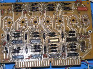
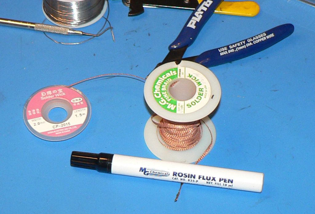
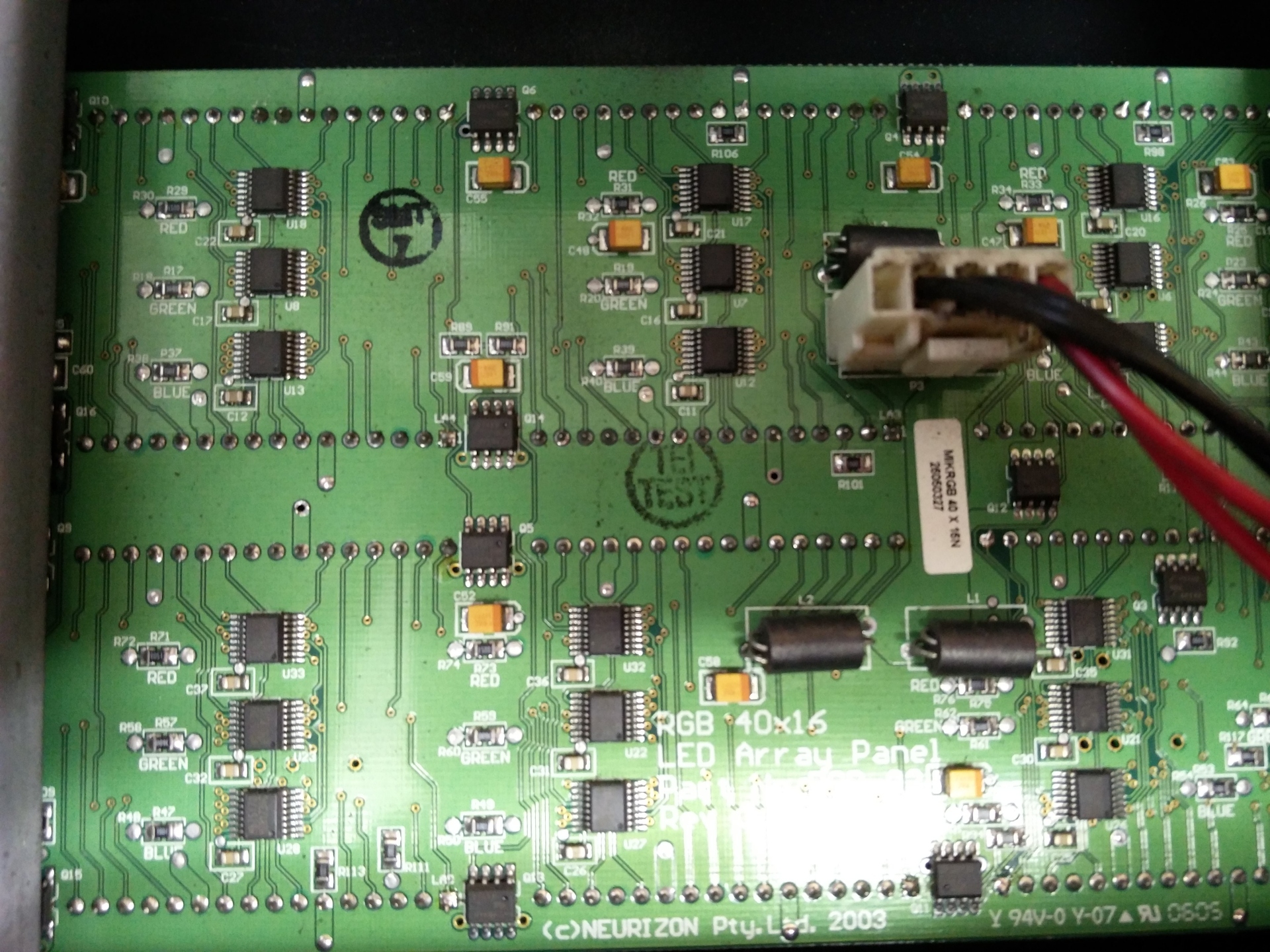
I had been thinking about doing a little project with nixies for a long time, but hadn’t really gotten around to it. They have a great old-school (old-fart?) vibe, and I found an old board on eBay with 7 nixies on it for cheap and decided that was a good place to start. It arrived (from Belarus), and I quickly realized how much faster this would go with a proper vacuum desolder tool, rather than just a sucker and some wick. Anyway, after much futzing around, I managed to get the little tubes off the board in prep for the next step. There are still some high voltage drivers left on that board I wouldn’t mind scavenging, but the board has a coating, and those intial 7 tubes just about killed me.

Nixies need 170V or so, and I didn’t much fancy the idea of rolling my own high-voltage power supply, so a quick check of the interwebs and sure enough there are a ton of them on places like eBay and Tindie. However, one that caught my attention as a better solution was a guy down in the states with a website tayloredge.com. Not only did he have some nice inexpensive (and tiny) power supplies, they also sell a very very nifty I2C nixie driver board. I had originally thought I might build a two digit module with the shift registers and drivers and sell it on Tindie myself, but wow, this is much better supporting direct addressing, shift modes, clock modes and even dimming. The density is crazy, with tiny SMD high voltage drivers, and a PIC controlling it all.

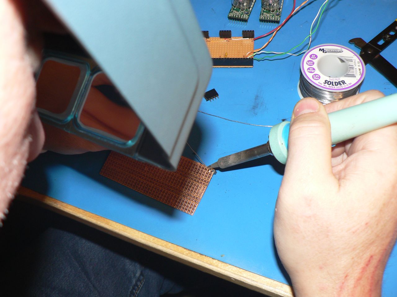
Like all good projects, all this stuff arrived months ago, and sat on my desk while I goofed off and did other things (Oscilloscope episode, coming soon !), and finally this weekend I decided to hook some of it up. First task was to make a mounting board that held four nixie modules (I only have two right now – I need to order more), so I cut up some advanced-vero-substitute (which really brings back old memories of Vero offcuts @ Greenweld), and build that into a mount that holds four digits, and strings together the necessary power (170, 5, GND) and I2C (SDA, SCL) lines.

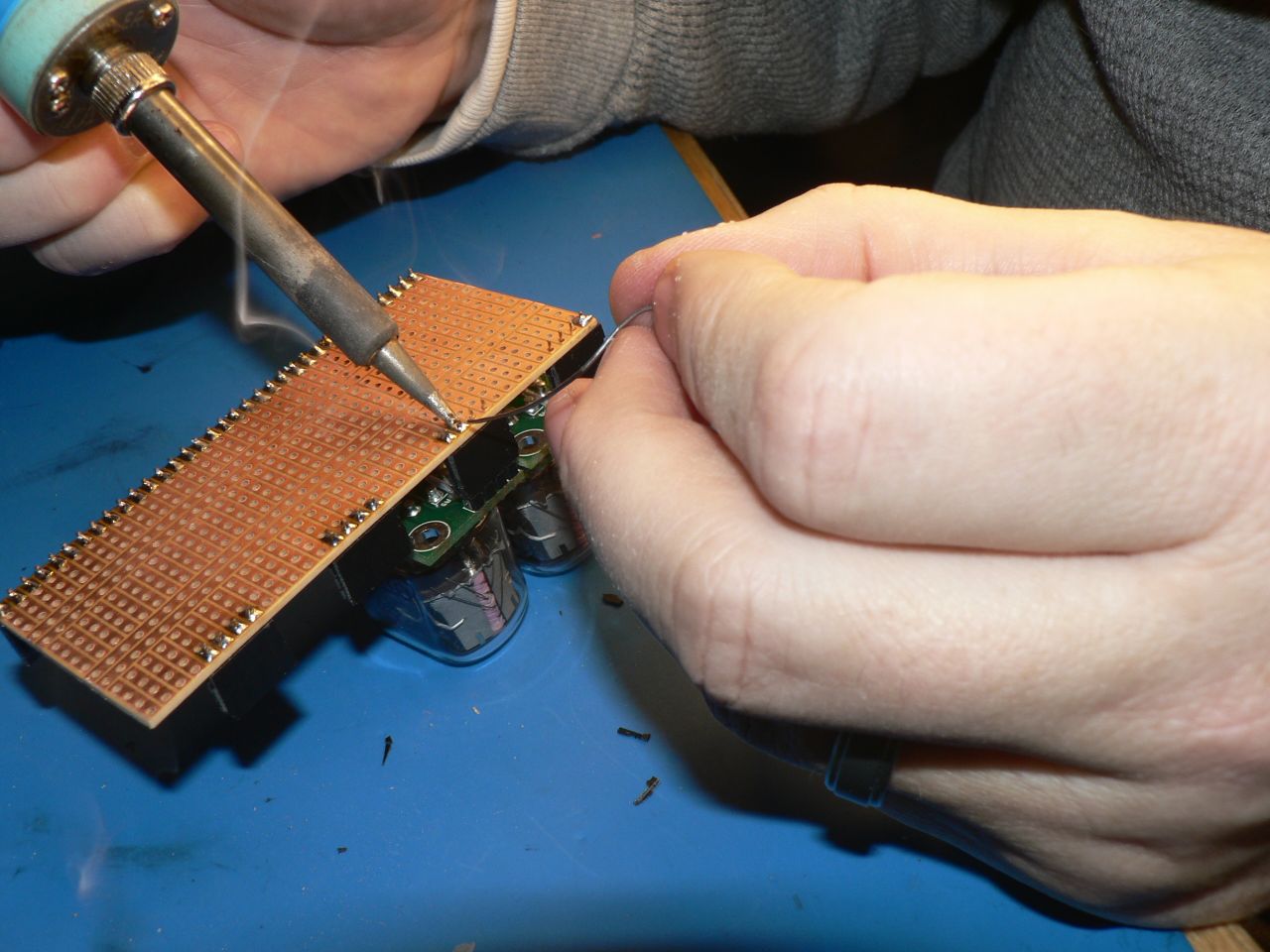
A little cutting, filing, and some 0.1″ headers soldered to the board and it works out pretty well. Eventually I want two boards of four, but for now I’ll get the first one hooked up, and then spend some time playing with the I2C interface. I tried really hard to get some action shots of the soldering but that’s pretty hard without an assistant, luckily Mrs Boffin was close at hand, so I did manage to capture at least one action shot.

In the end I decided to also add a couple of 0.1μF capacitors as well on the 5 volt rail, but it all went together fairly well, all I need to do now is repeat it on the second board. It really is nice to have a stock of things like the 0.1″ headers and caps, which I buy cheap in bulk from China/AliExpress.

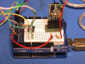
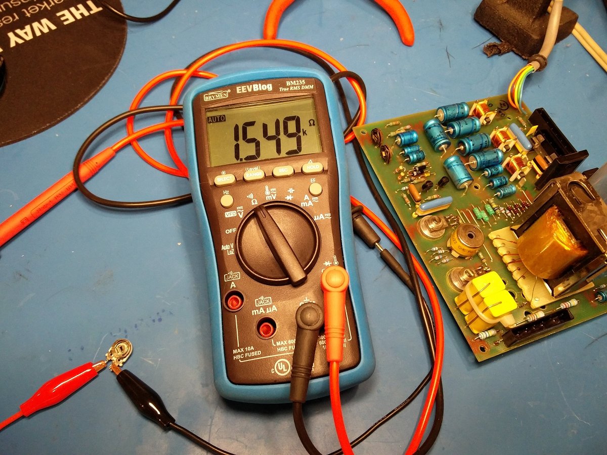
I had already tested out the power supply just on a bare nixie tube, and had learned that you needed a 47k voltage setting resistor as well as an enable jumper, so it was simple to put the power supply module on a little Arduino shield, along with the I2C pullups, and then I can just use that as a test jig. Amazingly the PSU works great from 5 volts with enough oomph to drive a couple of tubes, although I suspect in the final circuit with eight nixies, I’ll probably need to run the PSU from 9-12V.

Now the simple part, right? A little Arduino sketch that outputs the data to the tubes. Of course by this time it’s 11pm, and while it seemed straight forward from the Wire library in Arduino-land that this should be simple, things rarely are.

After everything was hooked up and on the board I was having all sorts of problems. Hey! This should be easy, set the address, send a register value, send a digit value. Not so fast bucko. First I managed to bend a pin on the bottom of the shield that connects it to the Arduino. Did I bend just any pin? No… I bent the ground pin, on the far side, bent into the middle, so it was impossible to see until I finally flipped the shield upside down, followed by a facepalm moment. Still with all of that working again, I could see that there was I2C data being sent, but nothing was showing up on the digits.

This should send a 5 to the first module:

Wire.beginTransmission(0x10);
Wire.write(0); // register
Wire.write(5); // value
Wire.endTransmission();

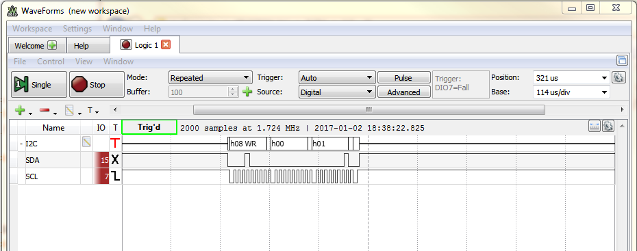
Nope, still no output on the tubes. After much head scratching, (and a 2nd glass of ginger beer), I decided it was time to dig out something that could actually decode what was going on on the I2C bus. So into the tool chest and out with the Analog Discovery USB oscilloscope I bought a couple of years back. I had picked this up off Kijiji from a student at USask that didn’t grasp the concept that the $100 student price he paid for it was WAAAY less than the $275 street price for us normal people. I see two or three every year going cheap this way. Anyway, it’s a fine tool, and while the bandwidth isn’t going to win any awards, it has built-in I2C  decoding on the 16 channel logic analyzer. Hey, what’s all that extra traffic happening? I didn’t put that there. Turns out it the module was set in clock mode (as opposed to address mode). WTF ?  The answer is that when they say “0 0 0 0” for the DIP switches, they really mean “ON ON ON ON” because they’re shorting to ground on pulled high inputs. OK, now we’re cookin’ with gas. Set it up to the self test setting, voila! It’s counting from 0-9. Set it back to the 1st address (0x10), but still my simple sketch isn’t doing the business, why not ?  I’ve set it to the correct address, I now understand the switch settings, why? why?  Well after playing with the sketch for different addresses, I discovered that when they say address 0x10 in the docs, they really mean half of that (I2C addresses are 7 bits and they were counting from the MSB apparently), Changing the address from 0x10 to 0x08 and it’s working YAY!

Once I got everything working, you can see clearly that the I2C address (at least from the Analog Discovery/Waveforms software) the address is and should be 0x08, not 0x10 for the 1st address. Easy fix in the code, and now I’ve got this sucker counting from 00-99 under my control.

Well, that was a weekend of 60 second fixes taking hours to find. Anyway, the first couple of digits are working, now to get 6 more modules (I’ve already got the nixies), and the 2nd carrier board built and we can move onto the next stage of the project.

Auction find; LED Sign

I pickFull RGB displayed up three of these interesting full RGB display signs from a local government auction; and while I haven’t done a lot of picking apart just yet, it looks like it’s completely tied to proprietary software. The company that built it the internals appears to be an Australian company that’s no longer in business. It’s beautifully bright, all the LEDs seem to work, and it’s powered by a very impressive 40 amp 5 volt power supply.  
sign2

All sorts of IO.  Ethernet (no I haven’t hooked it up to the home network just yet), RS232 (there’s a 485 in/out not shown in this photo as well). Some custom peripheral port, and weirdly there’s an audio input that goes to the logic board, but it doesn’t contain any audio display; I’m guessing there’s some software based way of having it do sound triggered/modified displays.

There’s a main CPU board, that drives a secondary board, and then three identical LED driver boards. Anyway, this will be my next project, and if I don’t get anything else out of it other than a 1000 bright RGB LEDs and a 200W 5V power supply, I’m still ahead.


LED Driver
One of three LED driver boards
CPU
Main CPU
all
The whole contraption

Update to the Serial Gauge

It’s been 8 months since I started selling on Tindie, and in that time I’ve managed to sell more serial gauges than I expected. I have received a little feedback from some of the purchasers, and based on that I’ve updated the software that drives the gauge to enhance a couple of things. The library now contains optimizations to use direct port mode, and main software has an option to set an initialization point. If you’ve got an old gauge, you can download the updated code from GitHub.

I’ve been thinking is there anything I want to add to this project?  Should I start a new project? What should I build? I know no one reads this blog, but if you’ve got ideas, please pass them along.


Wow, I should post more

power supplyTime sure flies.  I haven’t posted here in a while, but I thought I’d upload a few pictures of the most recent hack around the bench.  Took my old Radio ‘Battery Eliminator’ (12V, 3A), and converted it into a constant voltage/constant current supply using a little module I got from China (link here)

Moved the transformer inside the power supply back to make a little more room, and added a supply line fuse (it had an output fuse already).  Once that was done, I hacked the front to make the new module fit and added a couple of binding posts, making sure of the 0.75″ spacing (unlike the last time I hacked something like this), and I think it turned out rather well. I may still add an internal fan if it gets too warm, but I don’t use enough current out of it for that to likely be a problem.


power meter

I had also heard that these things weren’t particularly accurate, so I was curious to see how close it really was.  I hooked up an LED bulb (supposedly 2W, but closer to 1), and the current showed 94mA and the meter (Yes, the BM235 from EEVBlog) shows 96.1mA so about 2.5% off, but that’s close enough for the stuff I do.  It will be nice to be able to limit current, and also to have a quick current display to glance over at, rather than having to hook up a meter when I want to read it.

Of course the picture also shows my 1970s vintage Weller W-TCP-L, which is still going strong 40 years on. I’ve bought new tips (mostly use a 700 small chisel – for PCB work, and an 800F larger chisel – for bigger work), and it’s a champ.

Now to get back to what I came downstairs to do, pack up a Tindie order.  THANKS GUYS for all the support.  I’m not getting rich selling on Tindie, but it’s still a thrill to get an email saying “you have a new order!”

DIY hi hat controller for electronic drums

EDrum HiHatAbout 8 months back or so, I decided that I needed to learn how to play the drums. I’ve played the guitar for over 23 years, but needed something new, however, living in a condo I opted for a good, used electronic drum kit. As a fan of hard rock and heavy metal, one of the first things I bought was a double kick pedal to learn to play double bass. The one thing that was lacking however was the hi-hat cymbal’s controller could not be set into a fully closed position without my foot being on it – therefore, playing the hi-hat and double bass drum at the same time became not the best sounding or easiest thing to do.

A while ago, I got the bright idea to do some research around the internet and see if there might be any sort of electronic drop clutch that I could add onto the hi hat. After finding out how simple the hi hat controller foot pedal was (it’s essentially just a fancy potentiometer) – I realized what I had to do… make my own.

Continue reading “DIY hi hat controller for electronic drums”

Tindie – here I come

parts included
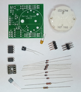
Well; I finally put the rest of my little stepper motor gauge project together and listed it on Tindie. Once they approve it, you should be able to find it by following the link at the top of the page to our Tindie Store.

The serial gauge driver allows you to retrofit any gauge mechanism with a simple to drive (any serial signal, it’s opto-isolated even) serial command stream.